


Knowing the basics of the CNC routing process helps you get the most from your CNC machine. If you are new to the possibilities of CNC routing, but wondering how to get started than this guide will hopefully point you in the right direction!
There are so many acronyms and technical terms related to CNC machining it can be confusing getting any kind of understanding of what is needed to actually make something! This guide breaks down the process from idea to actually holding a finished part in your hand.
I use the terms CNC Routing and CNC Milling interchangeably though you can argue about the definitions. However for the purposes of the beginner or maker or hobbyist the definitions the design process are similar.
What is a CNC Router?
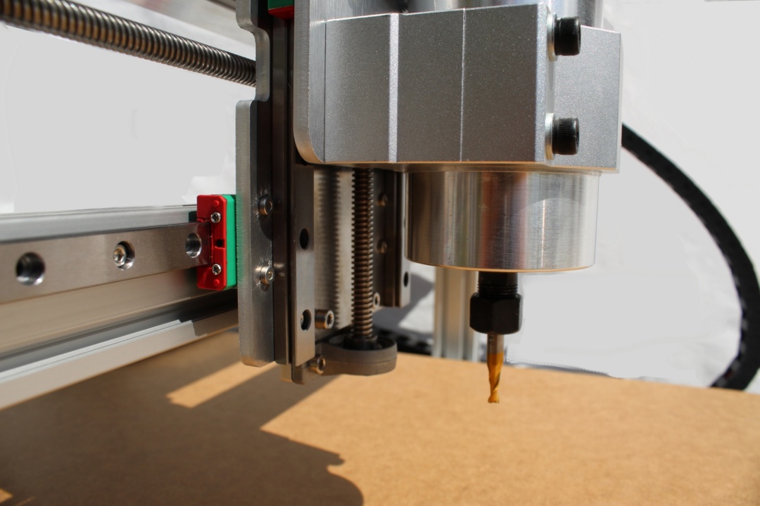
Generally speaking, a CNC router is a machine that has a traditional woodworking router mounted to a 3 axis frame. Often instead of a router a DC motor can be used. A CNC milling machine could be said to be more rigid and have a spindle with an inverter for speed control. Higher end CNC machines from manufacturers such as Haas or Tormach capable of machining steels are definitely in the CNC mill category, with a price tag to match.
However, whether you are a professional designer and CNC machine operator the process much the same for the keen maker as for the professional.
First, lets get a few acronyms out of the way. It’s hard to explain the CNC manufacturing unless a few key terms and commonly used acronyms are understood.
Essential Acronyms for Understanding the CNC Router Process
CNC/Computer Numerical Control
This is the automated method of controlling machine motion. Machines are programmed using a language that is G-Code
G-Code/Gcode
GCode is the language used to program machine motion. It can be programmed by hand or for more complex jobs, CAM software can be used. GCode is a text based format and is readable and editable in any text editor.
CAD
Computer Aided Design: This an be 2D or 3D software used to create designs and geometry that is used to define machining paths.
CAM
CAM stands for Computer Aided Machining or Computer Aided Machining and is an area of engineering concerned with using computers as tools to aid manufacturing.
GRBL
GRBL runs on microcontrollers and converts gcode to electronic signals that stepper motors controllers can understand. GRBL is the open source firmware used particularly on Arduino CNC based USB controllers. More information on GRBL can be found here.
Machine Controller
This is the software running on a PC or tablet that provides a human interface used to control the CNC machine. From here you can jog the machine, load, view and run jobs as well as viewing the machine status.
Infographic of the CNC Routing and Milling Process
You can break down the whole CNC manufacturing process into three stages as shown in the infographic below
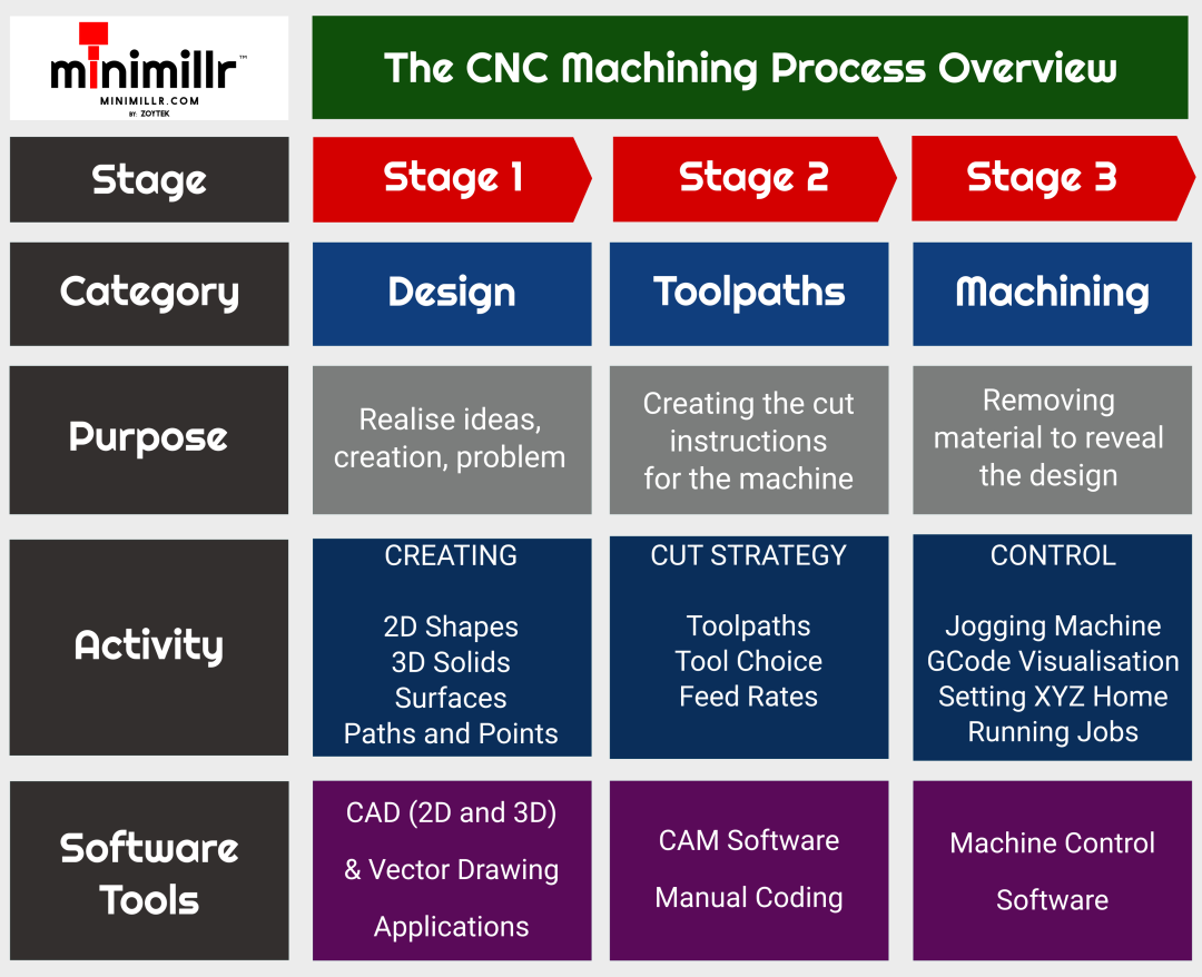
Stage 1: Design
This stage is about creating the item to be machined. These days it is most likely to be done in a CAD package or drawing program. You can also use existing designs available on the internet.
Depending on what is to be machined, the design can be 2D or 3D.
Usually the output from the stage will be a file that is used in the next stage to generate toolpaths.
Common File Formats
2D SVG: This stands for Scalable Vector Graphic, and is a 2D format that can be easily resized without loss of quality.
DXF/DWG: Common 2D CAD formats, also vector based.
STL: A ‘Standard Tessellation Logic’ or 3D triangular mesh file commonly used in 3D printing. STL files are a highly portable 3D surface format. Most 3D CAD/CAM programs can import STL files.
IGES: Short for ‘Initial Graphics Exchange Specification’, this 3D file is commonly used in 3D CAD programs as a neutral and geometry format.
STEP: Stands for ‘Standard for the Exchange of Product model data’. A bit of a mouthful, but this is also widely used format for storing and exchanging 3D CAD data for transfer between various CAD and CAM programs.
Stage 2: Toolpaths
Once you have a design file you are ready to generate tool paths. Tool paths to tell your CNC router what to machine. It’s important to think about a cut strategy for your part. Ask yourself which cuts should be first, and importantly how will the workpiece be held down on the router bed?
CNC Router Tool Choice
The type and size of cutting tool is important to ensure you get the result you are looking for. Common tools are end mills, V bit cutters and round nose end mills. Cutters come in various sizes and geometry and the best choice will depend on the type of material and the type of cutting required.
The right choice of tool depends on several factors including:
- The geometry of the part
- The material
- The type of finish required
- The power and accuracy of the machine
The target cycle time
CNC Router Feed Rates
The feed rate is important to ensure the router or spindle does not get over loaded. Cutting too fast can cause excess heat, poor finish and slipping of the axes where stepper motors can loose steps, and ruin a job.
Setting the feed rate too slow is also a problem as jobs can take far too long and on some plastic materials can cause melting and clogging of the cutter.
Finding the tool and feed speeds is often a case of trial and error. It’s best to try on a scrap piece first to be sure the feed settings are appropriate rather than diving in with the final workpiece. Once the settings are good you will have less waste and much better results.
When you have programmed the toolpaths, use a visualisation program to make sure everything looks OK. CAM program usually come with toolpath visualisation, but there are online tools such as GCode Viewer or Camiotics.
Once everything looks good, export you toolpaths as GCode file.
Stage 3: CNC Machining
OK, so you have a design. You’ve chosen a cutter. You have tested your feeds and speeds on a piece of scrap and your CNC router is ready for the finished piece.
Fix the workpiece securely and make sure it is level. There are many ways to hold a workpiece including:
- a vice
- clamps (rotary, step, arm, toggle)
- double sided tape
- vacuum
- superglue/gorrilla glue
- wood screws
- bolts
The best method depends on workpiece size and the choice of material. Make sure the cut paths will not interfere any of the clamps, screws or vices etc. Think about what happens as the cut progresses – use tabs to stop parts moving once finished.
Set the Z height of the cutter by jogging the CNC router to just above the material. It is usually best to set the home position on the top bottom left corner. Sometimes the centre of the piece makes more sense where there are circular cuts or designs.
Finally make sure to wear goggles and hearing protection. Use a shop vacuum to remove dust as the job progresses. It’s usually a good idea to supervise the job in progress to make sure everything is going as expected.
For an introduction to using the Minimillr range or CNC routers and mills, check the Quick Start Guide. If you want to use Inventables Easel CAD/CAM software with the Minimillr CNC machines see here. For an overview of using Minimillr machines with Candle, check out this page. There is also a list of free CAD/CAM and Machine Control software here:
So that is really high level overview of the CNC routing process. For more specific detail on the steps check out our other blog posts. Happy carving!